


Infrared Thermometers, Tài Liệu Hiệu Chuẩn
ĐLVN 124: 2003 – Quy Trình Hiệu Chuẩn Nhiệt Kế Bức Xạ Công Nghiệp
Th1
Industrial Radiation Thermometers – Methods and Means of Calibration
ĐLVN 124: 2003 – Quy Trình Hiệu Chuẩn Nhiệt Kế Bức Xạ Công Nghiệp
1. Phạm Vi Áp Dụng
Văn bản kỹ thuật này quy định phương pháp và phương tiện hiệu chuẩn các loại nhiệt kế bức xạ dùng trong công nghiệp, có phạm vi đo từ ( – 40 đến 2600 ) oC với các bước sóng hiệu dụng không vượt quá 30um.
Infrared Thermometer Calibration — A Complete Guide
With proper setup and planning, infrared thermometer calibrations can be accurate. The steps outlined below should be followed to perform accurate infrared thermometer calibrations. Much of the information presented here is contained in ASTM E2847, “Standard Practice for Calibration and Accuracy Verification of Wideband Infrared Thermometers.”
Sources of uncertainty
There are several sources of uncertainty which contribute greatly to an infrared thermometer calibration. These sources are summarized below.
- Emissivity estimation of the calibration source
- Field-of-view of the infrared thermometer
- Temperature gradients on the radiation source
- Improper alignment of the infrared thermometer
- Calibration temperature of the radiation source
- Ambient temperature
- Reflected temperature
Mandatory calibration equipment
The following equipment is a must for any infrared thermometer calibration.
- Thermal radiation source
- Transfer standard
- Ambient temperature thermometer
- Mounting device
- Distance measuring device
The thermal radiation source is a calibrated temperature source that provides radiation. The strength of the radiation is dependent on the source’s temperature; this radiation is what the infrared thermometer uses to determine temperature.
One of the major concerns in choosing a radiation source is how big it should be. Much of the concern is due to the infrared thermometer’s field-of-view. For Fluke Calibration infrared thermometers, a source size of 5 inches (125 millimeters) in diameter is enough for all models. For other manufacturers’ models, this information should come from the infrared thermometer manufacturer or be determined by experimentation.
The transfer standard is used to calibrate the thermal radiation source. The transfer standard must be traceable to BIPM through a national metrological institute. The transfer standard can be a contact thermometer (a PRT, thermistor, or thermocouple) or a non-contact thermometer (a radiation thermometer). The transfer standard may be implemented internal to the laboratory performing the infrared thermometer calibrations, or may be implemented using a third party laboratory external to the lab performing the infrared thermometer calibrations.
The ambient temperature thermometer is used to monitor the temperature inside the laboratory. This is especially important because for some infrared thermometers, ambient temperature plays a big role in uncertainty, as the ambient temperature affects the reference temperature of the infrared thermometer.
The mounting device is what holds the infrared thermometer during a calibration. The mounting device maintains the measuring distance and alignment of the infrared thermometer during calibration. The mounting device may be a tripod, a fixture, or a hand.
A device should be used to determine measuring distance. Measuring distance is the distance from the radiation source to the infrared thermometer. The distance measuring device will typically be a tape measure or a measuring rod.
Non-mandatory equipment
Depending on the infrared thermometer being calibrated and the calibration temperature, additional equipment may be required. Some infrared thermometers will need to be calibrated with an aperture. If this is the case, the aperture size and the measuring distance should be stated on the report of calibration. If a calibration point below the dew or frost point is made, a provision should be made to prevent ice or moisture build-up on the calibrator surface. This can be done via the use of a dry gas purge. In this case, the purge gas may be dried air, nitrogen, or argon.
Traceability schemes
There are two traceability schemes, Scheme I and Scheme II. The two schemes are classified by how the calibration source’s true temperature is determined. In Scheme I, the true temperature is determined by contact thermometry. In Scheme II, the true temperature of the source is determined by radiation thermometry. Scheme I would appear to be the best method to use; however, it is not. There are two generally large uncertainties that arise when using Scheme I: the emissivity uncertainty and the source heat exchange uncertainty. The use of Scheme II accounts for these errors. The 4180 and 4181 Precision Infrared Calibrators come from the factory with a Scheme II calibration.
Laboratory setup
In order to perform infrared thermometer calibrations with minimized uncertainties and minimized errors, a proper laboratory setup should be observed.
The temperature in the laboratory should be maintained within reasonable limits. The ambient temperature during the calibration or the laboratory’s temperature limits should be stated on the report of calibration. This is important as it provides the customer information about the environment that the infrared thermometer was calibrated in.
The positioning of equipment within the laboratory is critical. One of the biggest concerns is reflected temperature. This is especially a concern when conducting calibrations at lower temperatures. To properly account for reflected temperature, the following provisions should be made. First, never set up a laboratory so that a heat source is facing the radiation source. Second, make sure that the temperature of the walls facing the radiation source is that of the laboratory. This is especially a concern if the wall facing the radiation source is an exterior wall or an exterior window. Third, the position of the technician performing the calibration should be considered, since he/she influences the reflected temperature. For calibrations at temperature below 50 °C, a divider may need to be emplaced between the technician and the radiation source (see Figure 7).
Another concern in setup of a laboratory is ambient air flow. In no case should any forced air be near the surface of the radiation source. This means care should be taken not to set up the radiation source near (or beneath) any HVAC vents and doorways.
Examples of correct and incorrect laboratory set up are shown in Figure 6.
Calibration procedure
Preparation
Before the calibration, the infrared thermometer should be allowed enough time to reach the temperature of the laboratory, typically 15 minutes. This is an especially important consideration when bringing a thermometer in from the outside.
For most calibrations, cleaning the infrared thermometer’s lens is not recommended. Any lens cleaning that is done should be done with the permission of the customer and according to the infrared thermometer’s manufacturer’s recommendations.
The radiation source should be set to the desired calibration temperature and should be allowed to stabilize. If the calibration is to be done with a dry gas purge, the purge shall be set up before the radiation source stabilizes.
Calibration points
The customer should determine the calibration points used. They should be based on the customer’s wants and needs. If the customer does not know what calibration points he/she wants, the calibration laboratory may offer advice. If the infrared thermometer is used over a narrow range of temperature, one calibration point may be enough. For an infrared thermometer used over a wide range of temperatures, at least three points should be used. These points should represent at least the minimum, maximum and mid-range of the infrared thermometer’s usage range.
The order of the calibration points may be chosen in an arbitrary fashion. However, due to the phenomenon of thermal shock, it is best practice to perform the lower temperature calibration points first and the higher calibration points last.
Procedure
The following steps should be repeated for each calibration point.
If the infrared thermometer has a reflected temperature setting, it should be set to the radiation source’s reflected temperature. The reflected temperature setting may be called background temperature. It should be noted that Fluke infrared thermometers do not have a reflected temperature setting.
The emissivity setting of the infrared thermometer should be the same as the source’s calibrated emissivity. Some infrared thermometers have a fixed emissivity. In these cases a mathematical correction may be made. If a Fluke 4180 or 4181 is being used, this correction can be made automatically by the instrument.
The next step is to align the infrared thermometer. To do this, first set the measuring distance. For Fluke infrared thermometers, the measuring distance is set from the flat plate surface to the front housing of the infrared thermometer. The Fluke Calibration 4180 and 4181 provide a measurement point so that the calibrator surface does not have to be touched. The concave portion at the top of the display panel is within 1 mm of the calibrator surface. Measurements should be taken from this point as shown in Figure 8. Once the distance is set, the infrared thermometer should be centered on the calibrator surface. This can be done by using the laser provided with the infrared thermometer, or by maximizing the signal by moving the infrared thermometer up and down and side to side as shown in Figure 9. When alignment is completed, the line from the infrared thermometer to the calibrator surface should be no more than five degrees from normal (perpendicular).
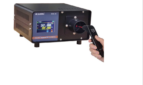
At this point, a measurement is ready to be made. The measurement should be initiated. The measurement time should be ten times longer that the infrared thermometer’s response time, typically five seconds for Fluke infrared thermometers. For Fluke infrared thermometers, the measurement is made by holding the trigger for five seconds. The resulting final readout temperature should be recorded as the readout temperature for the calibration.
In spite of the complex sounding nature of this method, the procedure is actually quite simple. For one measurement, it should take the calibration technician no longer than 15 seconds.
Uncertainty analysis
Uncertainty analysis is necessary for any calibration. This type of analysis is beyond the scope of this document. For a complete look at uncertainty analysis for infrared thermometer calibrations, consult ASTM E2847, “Standard Practice for Calibration and Accuracy Verification of Wideband Infrared Thermometers”. An example uncertainty budget is listed in Table 1.
| Uncertainty | Desig. | Type | U(100 °C) (°C) | |
|---|---|---|---|---|
| Source | Calibration temperature | U1 | B | 0.268 |
| Source emissivity | U2 | B | 0.128 | |
| Reflected ambient radiation | U3 | S | 0.031 | |
| Source heat exchange | U4 | B | 0.012 | |
| Ambient conditions | U5 | B | 0.001 | |
| Source uniformity | U6 | A | 0.163 | |
| InfraredThermometer | Size-of-source effect | U7 | B | 0.019 |
| Ambient temperature | U8 | A | 0.050 | |
| Atmospheric absorption | U9 | B | 0.020 | |
| Noise | U10 | A | 0.100 | |
| Display resolution | U11 | A | 0.058 | |
| Combined expanded uncertainty (k=2) | 0.364 |
Reporting your results
The report of calibration is a communications tool for you and your customer. The report should be in a standardized form and meet the requirements of your laboratory’s accrediting body. The results of the calibration should be reported. This is best represented by a table of source temperatures versus infrared thermometer readout values. An indication of PASS/FAIL may be made in this table as well. The report should include the following items:
- Title
- Unique identification of the calibrated infrared thermometer
- Record of the person who performed the calibration
- Date of calibration
- Source temperature versus infrared thermometer readout temperature
- Measuring distance
- Emissivity setting of the infrared thermometer
- Diameter of the source
- Ambient temperature
- Description of the aperture including aperture distance (if used)
- Measurement uncertainties
Other supplementary information such as a description of the calibration procedure, a list of reference instruments used, a statement regarding the traceability of the calibration, and a description of the uncertainty budget may be included in the report as well.
Additional learning resources
How to Calibrate an Infrared Thermometer on-demand webinar
Metrology 101: Infrared Thermometer Calibration application note
Infrared Temperature Calibration 101 application note
How to Create an Infrared Thermometer Uncertainty Budget on-demand webinar